Strandherd Armstrong Bridge Erection
LOCATION: Ottawa, ON
CLIENT: Horseshoe Hill Construction
VALUE: $50 M (Approximate)
YEAR: 2010-2014
ROLE: Bridge Erection Engineer
CATEGORY: Bridge
Strandherd Armstrong Bridge Erection
LOCATION: Ottawa, ON
CLIENT: Horseshoe Hill Construction
VALUE: $50 M (Approximate)
YEAR: 2010-2014
ROLE: Bridge Erection Engineer
CATEGORY: Bridge
Noteworthy Project Experience
Complex global phasing, innovative construction engineering, complex geometry control to satisfy strict tolerances.

Project Description
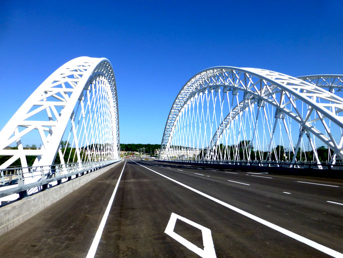
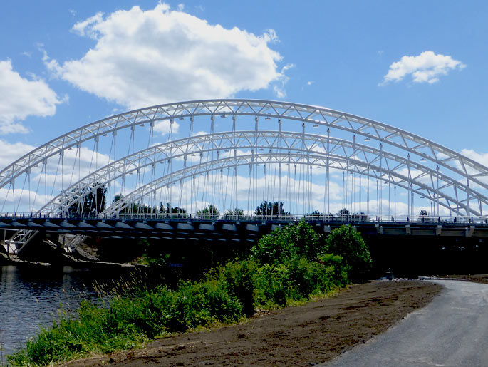
The Strandherd Armstrong Bridge is a multiple, space-truss arch bridge that spans across the Rideau River with a concrete deck supported by steel framing that is, in turn, suspended by cables. The total span of the completed bridge is 143 meters and accommodates 8 full traffic lanes, 2 bike paths and 2 pedestrian sidewalks. The arches rise above the deck level approximately 21 meters at their peak. The design of the bridge was completed by Delcan while the general contractor for the project was Horseshoe Hill Construction. Harbourside Engineering Consultants (HEC) provided the erection engineering for the project and had developed a unique method to erect the complex structure.
The unique erection method involves constructing 90% of the steel superstructure of the bridge on the east approach and launching it across the Rideau River. The approach limits the environmental impact at the site, is cost effective and has a positive impact on the schedule for the project.
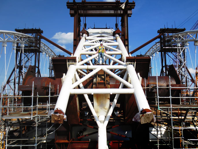
Each triangular, space-truss arch is composed of 3 chords made of 508 mm diameter round sections. The wall thicknesses of the chord elements vary from approximately 28 mm to 76 mm. A significant benefit of the erection approach is the ability to complete costly arch chord field splices and coating repairs while the superstructure is still over land and easily accessible.
The construction followed the general methodology described below:
- The final abutments/thrust block foundations for the arch are constructed (already complete) at both the east and west approaches.
- Twelve temporary support bents founded on drilled steel pipe piles are installed in the waterway respecting a well-defined navigation channel for boaters.
- Three box trusses, one centered on each arch, are constructed on the west approach and launched into position over the waterway and supported on the temporary bents.
- A steel rail system, supported on timber ties, is installed on the east approach.
- The steel superstructure is erected on the east approach including the steel deck framing and the space truss arches. The arches are supported on temporary shoring towers that are up to 25 meters high.
- The cable hangers are installed at a prescribed length such that under full dead loads, and considering both the elongation of the cables and the deflection of the arches, the deck falls to the desired final profile.
- Each end of each arch is supported by a unique transfer beam system that transfers gravity and wind loads down to the rail car / Hilman roller assemblies, while the arch horizontal thrust is resisted by post-tensioned bow string assemblies that are comprised of multi-low relaxation prestressing strand spanning from one end of each arch to the other. The horizontal bow string tie also allows for some minor adjustments to the position of the end of the arch for the final installation.
- After the deck is de-propped and the arch load transfer operation from the shoring towers to the transfer beam assemblies is completed, the superstructure is then launched, moving from east to west, into its final longitudinal position. The launch is accomplished using heavy duty Hilman rollers that roll first on the steel rails installed on the east approach and then on the top chord of the box trusses previously launched across the waterway (completed July 2013 in just under 2 days).
- At the completion of the launch, lifting towers are rapidly installed on the end temporary bents and the 2000 tonne superstructure is raised with 200 tonne (north and south exterior arches) and 400 tonne (center arch) strand jacks in order to allow the temporary box trusses to be de-launched back onto the west approach for dismantling and removal from site.
- The superstructure is lowered under control into its final vertical (and longitudinal) position and a field splice is made to a 5 meter section of arch cantilevered from the thrust block. Once the field splices are completed, the base plates are concreted into place on the thrust blocks and the anchor bolt nuts installed.
- The short approach spans are installed from both the east and west approaches.
- With the base plate concrete reaching strength, the load is transferred to the thrust blocks, and the transfer beam and bow string assemblies are removed.
- The concrete deck is cast and waterproofing and an asphalt wearing surface applied.
- The approach roads on both the east and west approaches are completed.
In addition to the design of all erection components, analysis of all components of the bridge structure for launch conditions (abutments, approaches and superstructure), and the comprehensive erection phasing package, HEC also provided the following services for this project:
- The design of formwork supports for the thrust block anchor bolts and suspended CIP reinforced concrete temporary pile caps;
- Navigation drawings;
- An alternate design for the arch base plate assemblies to improve constructability and significantly increase construction tolerances;
- Calibration / tuning of arch hangers and determination of hanger lengths such that the arches are plumb and the deck falls to the correct profile when all dead loads are applied;
- Modern PSS cable-stay system project specialist;
- Deck casting sequence and screed elevations;
- Determination of arch segment coordinates for installation of the arches on the east approach shoring towers, including the arch installation procedure, coordinate thermal corrections and anticipated weld shrinkage;
- Determination of as-built arch end segment lengths, accounting for the as-built arch, thrust block, and anchor bolt tolerances;
- Review of the as-built arch and hanger conditions, reporting all tolerances to the contractor to verify that arch construction meets the requirements of the project specifications;
- Detailed temporary works removal procedures;
- Inspection and sign off on all constructed temporary works; and
- Review of shop drawings and responses to non-conformance reports.
On behalf of the steel fabricator, HEC also conducted an in-depth analysis of the effect of the cold bending of the heavy walled pipe sections used as chord elements in the space truss arches. HEC developed a theoretical method of predicting residual stresses present on the cross section of the element due to the cold bending process. The theoretical method included a prediction of the residual strains present after cold bending. The residual strains were verified by testing (strain gauge measurements) of the chord section in production. The recommendations set forth by HEC included a method to incorporate the residual stress data into the design and analysis methods prescribed by CAN/CSA S6-06 such that the effect of the cold bending process could be readily incorporated into the analysis of the arch chord elements.
This innovative design and erection method won the 2014 Engineers Nova Scotia Lieutenant Governor’s Award for Excellence in Engineering.
The structure was completed and opened to traffic July 12, 2014.