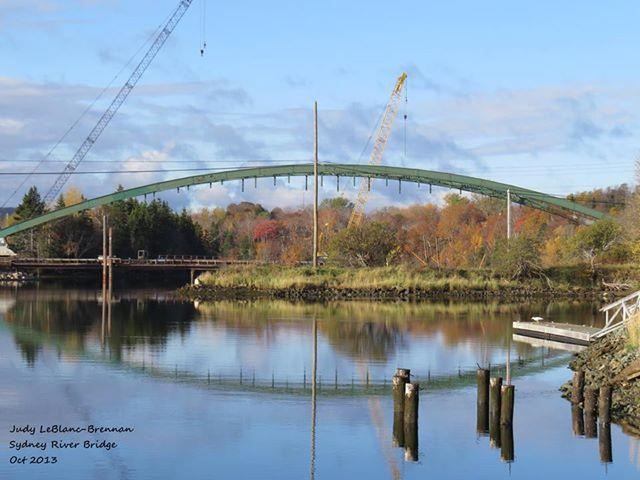
Sydney River Bridge Demolition
LOCATION: Sydney, NS
CLIENT: Caldwell & Ross
VALUE: $2.0 M (Approximate)
YEAR: 2013
ROLE: Demolition Design (Joint Venture with Caldwell & Ross)
CATEGORY: Bridge
Sydney River Bridge Demolition
LOCATION: Sydney, NS
CLIENT: Caldwell & Ross
VALUE: $2.0 M (Approximate)
YEAR: 2013
ROLE: Demolition Design (Joint Venture with Caldwell & Ross)
CATEGORY: Bridge
Project Description
The Sydney River Bridge was constructed between 1957 & 1958 and consisted solely of a 130.1m long main span solid ribbed / two pin steel arch span. In December of 2009 & January of 2010, HEC completed an OSIM inspection of the structure followed by a full structural assessment and development of retrofit / replacement options. The findings of HEC’s analysis and preliminary design report submitted to NSTIR ultimately led to the decision for a demolition of the existing structure proceeded by a replacement. The design of the replacement structure (also completed by HEC) was issued for tender and construction of the replacement along with demolition of the existing was awarded to Caldwell & Ross, based in Fredericton, NB.

Phase I of the demolition involved the balanced removal of the concrete deck, supporting steel grillage and hangers using 2 – Kobelco SK260LC Excavators and 2 – Caterpillar IT38G Integrated Tool Carriers. The two excavators were used to lift the removed steel and concrete sections as they were cut, while the tool carriers were used to drag the demolished sections off the structure along the deck. Phase I of the demolition was balanced because the demolition of the deck and supporting steel along the length of the structure was required to be symmetrical about the center of the structure in both the North and South directions to minimize strong axis bending moments in the arches and ensure an in-plane / snap through buckling mode of the arch did not occur. The allowable positions of the equipment on the deck was also fully detailed to ensure a critical buckling state in the overstressed arches was not triggered.
Phase II of the demolition was developed in conjunction with Caldwell & Ross. HEC’s scope for Phase II was to design a procedure to relieve the thrust from the arch and vertically support the arches on three steel pipe pile support bents (bents designed by Caldwell & Ross). The pile bents were effectively positioned at quarter points along the length of the arch and HEC provided reaction tables to Caldwell & Ross for the design of the bents.
The arch load relief assembly consisted of two jacking frames, each equipped with 4 – 100 ton Hydraulic cylinder jacks that were connected to the arches at 13.6m south of the center of the structure. The jacks were loaded to locally counteract the anticipated compression in the arch, so the arches could be severed while avoiding any kind of sudden load relief that could potentially dynamically load the pile bent supports or injure personnel tasked with cutting the arches.
The arches were then flame cut at the load relief assemblies, jack pressures were relieved slowly and evenly until the arches were fully supported by the pile bents and the pins at the end thrust blocks. In order to resist lateral wind loads following the severing of the arches, ring connector plates were developed and installed at the pins to provide tension resistance.